
Hardline Sizes & Field Identification
Hardline in the Cascade
Hardline coax is the trunk medium between node, amplifiers, taps, and major passives. Unlike flexible drop cable, hardline uses a solid or semi-solid center conductor, foam dielectric, corrugated outer conductor, and thick PE jacket — built for decades of aerial or underground service with flooding against moisture.
Designers pick size based on span length, amp spacing, tap loading, and frequency plan. Larger cable = lower attenuation but higher cost, weight, and minimum bend radius. Wrong size identification leads to wrong tools — and destroyed cable ends.
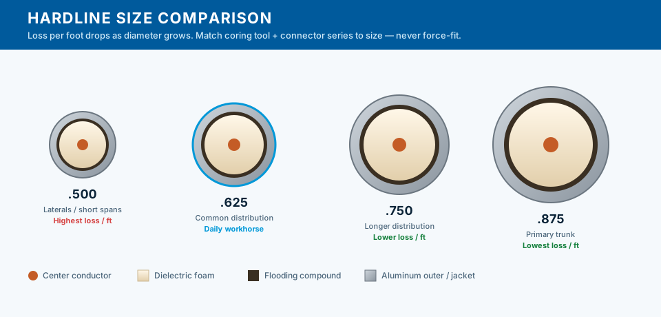
Common hardline series
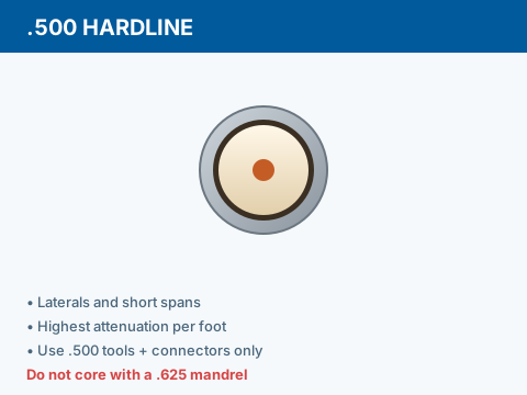
.500
Smallest common trunk. Short spans, laterals, legacy plant. Highest loss per 100 ft — limits unrepeated distance.
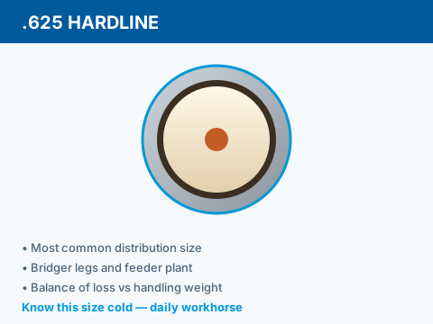
.625
Workhorse distribution size. Good balance of weight, bend radius, and loss on typical suburban cascades.
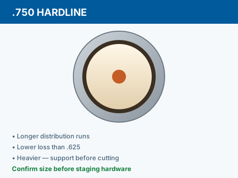
.750
Heavier trunk for longer spans between amps. Common on main feeders from node outward.
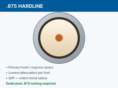
.875
Large feeder hardline; lowest attenuation per foot. Justified where long unrepeated runs offset material cost.
Match cable size to tools and connectors
Select a material, then its definition.
Materials
Definitions
Attenuation trend (use manufacturer charts)
- .500 @ ~750 MHz
- Often ~4–5 dB / 100 ft
- .625 @ ~750 MHz
- Often ~3.5–4 dB / 100 ft
- .750 @ ~750 MHz
- Often ~3–3.5 dB / 100 ft
- .875 @ ~750 MHz
- Often ~2.5–3 dB / 100 ft
- Frequency effect
- Loss increases with frequency — high-split plans stress upper band edges
Reading Jacket Print
Jacket is printed with manufacturer, series, impedance, date code, and footage marks. Sun-faded print may require cleaner or reading the next leg. If print is gone, measure outer diameter with calipers — .625 and .750 are not reliably distinguished by eye alone.
Never guess size to save a trip for the correct mandrel. One wrong core ruins the end and wastes trunk length. Document cable type on splice tags per job standard.
Using .625 tools on .750 cable tears dielectric and leaves an oversized seizure zone that will never seal. Verify size from print, caliper, or known reel tag before cutting.