
Equipment lab
See what we work with
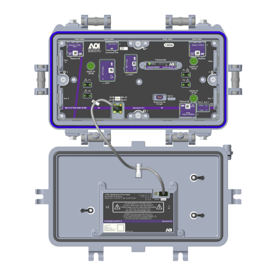
The high-split upgrade installs the AOI QuantumLink line extender in place of legacy amps. Get familiar with the AOI platform, taps, cable anatomy, coring, splice defects, and pad math before you touch plant.
Unplug the lid power interconnect before removing the RF module. Hardline ports can still carry 60/90 VAC plant power — treat seizures as energized until verified.
AOI QuantumLink LE / system amp
The open AOI QuantumLink housing: top half is the RF chassis (diplexers, trims, test points); the bottom lid holds the power supply. This is the platform we install on the high-split upgrade in place of legacy line extenders.
Walkthrough of the AOI amplifier / node platform we install on the high-split upgrade.
Retrofit an AOI amplifier into an existing Motorola housing — the field swap we perform.
How QuantumLink telemetry gives the NOC remote status and management of the plant.
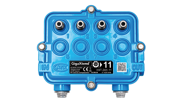
Directional tap — ATX GigaXtend
Hardline enters IN and continues out OUT. Drop ports feed customers. Tap value (dB) must match the strand map. Terminate unused F-ports on high-split return.
Pad & test-point calculator
Pads remove flat level. Meter at a TP reads below true RF by the coupling loss (often −20 dB).
True level ≈ meter + TP loss. Example: -9.0 + 20 ≈ 11.0 dBmV.
Signal flow trainer
Forward (downstream): services travel toward the customer. Click each stage.
QAM + DOCSIS origin; reverse terminates at CMTS/CCAP
Hardline cable breakdown
Side cutaway or end cross-section. Click every layer — each one has a prep job and a failure mode.
Black polyethylene outer skin. UV and abrasion protection for aerial or underground plant. Printed with size (.500–.875), manufacturer, and footage marks.
Read the print before you cut. Jacket nicks let water migrate under the PE and start corrosion months later.
1 / 5 layers reviewed
Coring sequence — animated
Accurate field sequence — square cut → seat → core to stop → inspect. Pause and step through each gate.
Confirm cable size from jacket print or caliper. Square-cut with hardline cutters so the end face is round and perpendicular — oval or angled faces side-load the coring tool.
Egg-shaped ends get cut again. Do not force a tool onto a crushed face.
How the size-matched coring / stripping tool prepares a hardline end in one pass.
Full underground straight splice — coring, pin, connector, and weatherproofing in sequence.
Splice defect drill — field splicer gate
Field splicers get paid to catch these before the housing closes. Open every card.
Knife mark, nick, or shiny groove on copper/clad conductor after cleanup.
Intermittent open under temperature swing; micro-reflections; rainy-day return noise.
Cut back past the score. Re-square, re-core with a sharp blade. Never file a nick 'smooth enough.'
1 / 6 defect types reviewed