
Photo-First Prep, Diplexers & Pad/EQ Theory
Balance Is Engineering Discipline, Not Memory
Amplifier replacement without a balance plan creates chasing levels across a node. Every tech who follows you should see the same evidence chain: photos before disconnect, module labels, diplexer part numbers, final pad/EQ settings, and meter results.
Copying old pad values onto a new module family is a common failure mode. Gain slope, internal pad location, and ALC behavior differ between legacy inserts and AOI QuantumLink-class hardware. Photos are a starting point; meter proof is the finish line.
High-split adds a non-negotiable gate: diplexer kit must match deployed split before power is applied. Wrong diplexers destroy upstream while forward may partially function.
Unplug power supply interconnect in housing lid before touching RF modules or diplexers. Verify de-energized per procedure. Opening a live housing risks shock and shorting plant power.
Photo-first documentation (before disconnect)
- 1Wide shot of housing interior showing jumper routing and port labels
- 2Close-up of each pad value (forward and reverse paths)
- 3EQ settings or switch positions on module
- 4Diplexer part numbers and orientation arrows
- 5Forward and reverse TP meter readings with TP label visible
- 6Power supply label and LED state; monitoring dongle presence
- 7Strand/pole ID and housing tag matching work order
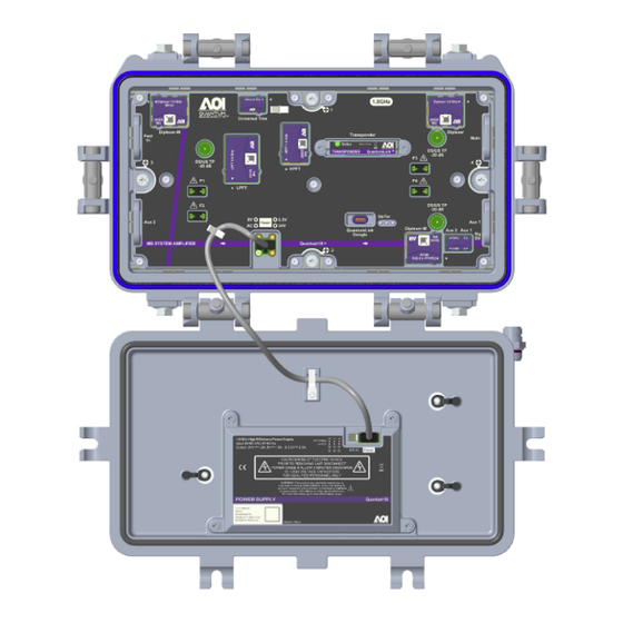
QuantumLink telemetry: how the NOC sees levels, power, and alarms after a balance.
Pad and EQ selection job aid
- Pads
- Discrete attenuation (1–12 dB typical) — forward reduces output to target; reverse adjusts CMTS window
- EQ
- Frequency slope correction (tilt) — not a volume knob; sweep/OneCheck tilt subtest guides setting
- Pad first rule
- Pad for level; EQ for slope — do not max EQ to fix low forward level
- Reverse tuning
- Fix ingress before reverse pad games — clean return path first
- High-split diplexer
- Compare BOM to labels before power; arrows align with IN/OUT trunk flow
Pad and EQ planning calculator
Pads remove flat level. Meter at a TP reads below true RF by the coupling loss (often −20 dB).
True level ≈ meter + TP loss. Example: -9.0 + 20 ≈ 11.0 dBmV.
ALC vs MAN — gain control modes
- ALC (Automatic Level Control)
- Module adjusts gain to maintain set output as input varies — common default on modern LE inserts
- MAN (Manual)
- Fixed gain; tech sets pads/EQ for balance — used when ALC hunting or engineering specifies manual
- When ALC misleads
- Low input from upstream fault — ALC maxes gain and hides upstream deficiency until noise rises
- Field practice
- Fix upstream input before tuning ALC setpoint; document mode on closeout sheet
- LED correlation
- Some platforms blink specific patterns when ALC out of range — check module guide