
Cut-Mark Method & Full Workflow
Prep Is a System
Cable prep is the complete process from uncut hardline to a torqued, sealed connector ready for RF. It begins with the connector manufacturer's cut chart — not tribal knowledge. Each family specifies jacket strip, coring depth, chamfer requirements, hardware slide order, and torque.
Professional prep looks identical every time: square face, concentric conductor, flood-free seizure zone, positive stop felt, torque verified, heat shrink uniform. Skipping inspection externalizes cost to rainy-night ingress troubleshooting.
The coring step, animated — where most preps go wrong
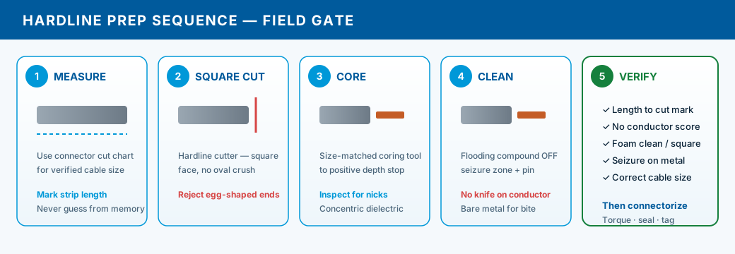
Accurate field sequence — square cut → seat → core to stop → inspect. Pause and step through each gate.
Confirm cable size from jacket print or caliper. Square-cut with hardline cutters so the end face is round and perpendicular — oval or angled faces side-load the coring tool.
Egg-shaped ends get cut again. Do not force a tool onto a crushed face.
Full underground straight splice: coring, pin, connector, and weatherproofing in field sequence — connector install follows only after visual pass.
Cut-Mark Method & Size Differences
Measure from the square-cut end using chart dimensions — not the last splice you remember. Mark jacket strip with fine marker or measuring jig. Cut jacket and outer conductor to strip length; deburr without beveling past spec.
.625 and .750 connectors look similar in the bin but have different body diameters, mandrels, strip lengths, and torque values. When plant maps call for .750 feeder but a lateral is .625, each end gets its own chart — do not average dimensions.
Full prep workflow
- 1Verify cable size (print, caliper, map); select connector family and cut chart
- 2Square-cut cable; measure and mark jacket/outer strip per chart
- 3Remove jacket and outer conductor to strip length; deburr
- 4Core with size-matched tool to depth stop; remove slug
- 5Clean all flood compound; inspect conductor and dielectric — reject if defective
- 6Install pin/bullet; stage O-rings, seizure, back nut in order
- 7Seat in connector body to positive stop; torque to spec
- 8Apply heat shrink on inlines; tag splice per job standard
Manufacturers account for dielectric compression and seizure travel in strip length. Shortening strip to 'make it fit' moves seizure onto jacket — intermittent shield faults meters miss until ingress fails.