
LE Role & QuantumLink Internals
What a Line Extender Does
A line extender (LE) is an inline trunk amplifier — receives forward and reverse RF, provides controlled gain each direction, retransmits downstream. LEs recover level lost to cable attenuation, tap through loss, and splitter loading since the previous node or amplifier.
LEs are spaced per design — not whenever level 'looks low.' Adding an unplanned LE without engineering raises noise floor across the segment. The node is the optical boundary; LEs are mid-cascade coax active devices.
Gain (dB) restores downstream and return level. Tilt (slope) compensates for frequency-dependent coax loss. Noise figure: each LE adds noise — cascade noise adds. Clean connectors upstream matter.
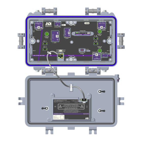
Overview of the AOI amplifier platform we install on the high-split upgrade.
QuantumLink Internals & Diplexers
QuantumLink: removable RF module, diplexer/filter assemblies, pad/EQ switches, test points, status LEDs, lid-mounted power supply via interconnect cable.
Forward: input → diplexer → gain → pad/EQ → output. Reverse: separate diplexer low-pass → return gain → upstream. Diplexer kit must match deployed split — legacy 42 MHz on high-split module blocks expanded upstream.
Test points sample output with fixed coupling — commonly −20 dB. +32 dBmV at forward TP ≈ +52 dBmV output. Always read TP label — offsets vary.
LE service quick reference
- TP offset
- Often −20 dB — verify module label
- Diplexer kit
- Must match deployed split (high-split vs legacy)
- First disconnect
- PS interconnect in lid
- Ingress first
- Fix before raising return gain
- Closeout test
- OneCheck/sweep per job package
Unplug PS interconnect before RF module contact. Opening housing with live interconnect risks shock and short across terminals.