
Splitters, DCs & Loss
Passives in the Plant
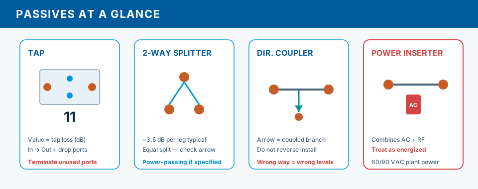
Passives divide, combine, or inject signals without amplification — every passive adds loss. They appear in amplifier housings, pedestals, power cabinets, and strand enclosures.
Splitters divide power equally (within tolerance) to multiple outputs. Directional couplers (DCs) preferentially couple energy to a branch while passing most on the through path — similar philosophy to taps but at different power levels and form factors.
Power inserters couple DC from a supply onto trunk coax while maintaining RF paths. Mis-oriented passives pass DC but fail RF — or vice versa.
Typical splitter loss (approximate)
- 2-way per leg
- ~3.5–4 dB + excess loss
- 3-way per leg
- ~5–6 dB + excess loss (verify mfr)
- Isolation
- High between outputs when wired correctly
- Power passing
- Most pedestal splitters block DC — know exceptions
- Unused port
- Terminate with 75 Ω — never leave open
Splitters & Directional Couplers
2-way splitter: ~3.5–4 dB loss per leg plus excess. 3-way legs vary — read datasheet. Reversing splitter (feeding output as input) destroys isolation — one leg hot, another starves modems.
Stacked splitters multiply loss: two 2-ways in series can exceed 7 dB before drop cable. DC ports: IN, OUT, COUPLED (and sometimes ISO). Swapping COUPLED and OUT changes coupling ratio.
Directivity (dB) describes isolation between coupled and through paths for reverse energy — low directivity or reversed DC lets branch ingress pollute trunk inside housing.
Pedestal with 2-way feeding two 2-ways can stack 7+ dB before drop cable. Trunk can look fine while modems starve — always account for passive loss to drop.
Reversed splitter or DC shows continuity to a DMM on center but wrong RF division. Photo labels; restore IN/OUT/CPL per print.